Abstract
In recent years, the LED lighting products have attracted more and more attention due to the low power consumption, long service life, high brightness, low thermal energy, environmentally-friendly performance, durability, rich colors, diverse appearances, stable performance, etc. They are developed from the outdoor to indoor lighting application market. The “high reliability” has become the most important feature of LED products and is directly constrained by the quality of the LED power supply.
Introduction
At present, the CR and CV modes are generally used in tests of the LED constant-current power supply industry. However, the majority of LED drive power supplies are designed according to the switching principle, with large current and voltage ripples, and the general CR and CV modes are easily subject to interference of high-frequency noise to result in test deviations and even failure of tests. According to the working characteristics, the LED light has the conduction voltage Vd. Only the working voltage of the LED light can be simulated by the CV mode of the electronic load, but the conduction voltage Vd cannot be simulated. Therefore, when the LED driver power supply is tested through the CV mode of the electronic load, the test results are not accurate enough.
Currently, the dedicated electronic load for the LED power supply test is often used to test the LED driver power supply. It has the advanced CR-LED mode. In general, one electronic load can be judged from the following three perspectives to be used in the test of the LED driver power supply.
(1) Check whether the CR-LED with the pure hardware circuit design is provided.
(2) Check whether the PWM dimming test can be done.
(3) Check whether the current pulsation of the LED driver and the transient surge current of start-up can be tested.
First, why is the CR-LED mode with the pure hardware circuit design is needed?
At present, the value R is obtained through the MCU processing unit and by means of software computing according to the AD sampling voltage and current in the CR or LED mode of main electronic load products on the market, with relatively slow response. The closed-loop control based on resistance calculations is limited by the speed of the processor, analog-digital converter, etc. Theoretically a certain delay exists. Therefore, this mode is only applicable to the products with low input changes and slow response.
In sum, the CR mode of the majority of general electronic loads is not supported by the actual hardware circuit, and the value is obtained by testing the voltage and current. As mentioned above, the LED constant current power supply has large high-frequency ripples, and the superimposed voltage changes in a real-time manner, resulting in failure of prompt response of the electronic load. In other words, when the CR value of the load under the current voltage is calculated through the electronic load, the actual voltage changes, therefore, the measured current is subject to constant fluctuations. This is a problem of common electronic loads, but the CR-LED mode with the pure hardware circuit design is free from this problem. The ITECH IT8912E (500V/15A/300W) electronic load is a dedicated electronic load with the pure hardware circuit design for the LED power supply test. It is compatible with various LED constant current power supply tests.
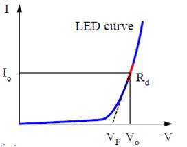
Simple setting steps can be provided based on the CR-LED mode with the pure hardware circuit design. The Rd value changes slightly for LED lights of the same type. The following figure shows the VI characteristic curve of the light-emitting diode.

VI Characteristic Curve of Light-emitting Diode
Inference: V0=VF+I0*Rd Where: VF=aV0 (a<1)
Thus, V0=aV0+I0*Rd----- (1-a) V0=I0*Rd------Rd= (1-a) V0/I0=coeff V0/I0.
When the LED constant-current power supply is used for supplying power to LED lights in series in the actual application, the working voltage increases with the number of LED lights in series increasing, and the working voltage of the LED lights is V0 in the above formula. For the CR mode of ordinary electronic loads, the value Rd should be calculated according to the voltage each time. For the ITECH IT8912E electronic load, the value Rd can be obtained by multiplying a reasonable coefficient coeff by the set parameter V0 and I0.
Example: the input voltage range of the LED constant-current power supply is 35V-65V, the constant-current output is 200mA, and the coefficient coeff is generally set between 0.1 and 0.2 (sometimes subject to fine tuning with coeff less than 1 for different LED constant-current power supplies). When the IT8912E electronic load is used, the test can be done by setting V0 (between 35V and 65V, with difference values corresponding to simulation of different lamp beads in series), with I0 as 200mA and coeff as 0.17.
Second, why the PWM dimming test is needed for the electronic load used in the professional LED driver power supply test?
PWM (Pulse Width Modulation) is the most commonly used digital dimming method. The light intensity can be changed by changing the set period and duty cycle. When PWM is at the high level, LED can emit light; otherwise, LED cannot emit light. Therefore, the brightness of the LED light can be adjusted by adjusting the duty cycle of PWM.
The LED light can be widely used, such as the streetlamp, LED searchlight, stage light, tunnel light, etc. The light intensity should be adjusted according to the site conditions in most cases. PWM dimming is one of the most commonly used methods. The drive current in the electrical characteristic table of the LED light can guarantee the light wavelength or display corresponding to the specific drive current. When the display screen is formed with a number of LED lights, the consistent rendering index and light color can be guaranteed.
With the PWM dimming function, the ITECH IT8912E electronic load can output the 20Hz-2KHz pulse signal to the dimming signal port of the LED constant-current power supply.

Finally, the function of testing the current pulsation of the LED Driver and the transient surge current of start-up should be provided.
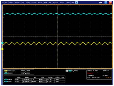
The working current of the LED light is generally dozens to hundreds of milliamperes. If the LED driver power supply generates too high current during start-up, the service life will be affected and the LED may be burnt directly in serious cases. The strict indicator of the start-up surge current is provided for the design of the LED driver power supply. Therefore, the electronic load for professional testing of the LED power supply should have the function of testing the surge current. When used with PC, the ITECHIT8912E electronic load can help the user to complete the surge current test.
For the IT8912E electronic load, the voltage and current measurement rate is 50KHz, the sampling rate reaches the us level, and the maximum current within a certain period can be collected and compared automatically. The engineer only needs to read the maximum current through PC according to the instructions to obtain the transient surge current of start-up and analyze the design indicator of the LED constant-current power supply.

ITECH IT8912E LED DC Electronic Load for Power Supply Test
As the power supply to drive the LED light, a special electroluminescent device, the LED power supply should be tested through the dedicated electronic load. The ITECHIT8912E electronic load can be applied in the research, development, production and quality analysis of LED constant-current power supply manufacturers to analyze the constant-current output parameters (voltage and current) and start-up characteristic indicators of LED. For the LED driver with dimming features, no additional digital signal source is required, and the PWM pulse waves output by IT8912E can be used for the dimming test, thereby saving the costs of customers and simplifying test steps. They are common goals of all test solutions of ITECH.

